Ultrasonic welding of thermoplastics
Apr 08, 2022
Ultrasonic welding
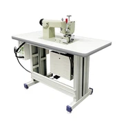
The most common method of welding thermoplastic parts is ultrasonic welding. In this method, low amplitude, high frequency (ultrasonic) vibration energy is used to cause surface and molecular friction to generate the heat required to weld the plastic parts of the joint pad. (Sinusoidal ultrasonic vibration) Ultrasonic welding occurs in the frequency range of 20-50khz, with a general amplitude range of 15-60um. Audio frequencies as low as 15kHz(higher amplitude) are sometimes used for larger pieces or softer materials. The welding process usually takes place within 0.5-1.5s. The amount of welding process includes welding time, welding head position and welding pressure. Ultrasonic welding equipment is usually used for welding small size thermoplastic parts, and large parts can be multipoint welding.
Ultrasonic welding methods can be controlled according to welding time or weld position (collapse distance) or welding energy. Additional controls are also provided for welding pressure and cooling time. Ultrasonic welding equipment generally operates at either 20kHz or 40kHz frequency. 20kHz devices are more commonly used.
Joint design: The first type, the most common type of joint, utilizes ultrasonic vibration in the vertical direction of the connected surface. Docking and Z-conjugation fall under this category and apply to most polymers. The second type of ultrasonic welded joint involves vibration parallel to the surface of the joint, forming a shear state. Various types of clipping and nesting fall into the second category.
The energy controller contacts are best used with amorphous materials, and larger energy controller junctions can be used in some unsealed semi-crystalline materials. The following model is modified with a rough or textured surface. This will improve welding quality, strength and ease of completion. Many other textured joint shapes are also available. The overflow problem can be reduced by introducing the overflow contamination tank into the connection design. For safety, the overflow tank is generally designed with at least 10% excess volume capacity.
Compression joints: To minimize the possibility of overflow formation, compression joints are designed to block or hold melt in the melt zone. Compression joints are useful for semi-crystalline plastic materials such as nylon. Because of the more complex structure of the close, the fitting tolerance of the parts required for the tight close is relatively strict. Larger joint structures also require additional amplitude and welding energy compared to triangular energy-guided clamshell welding.
Pieces leveling, simple docking there is no solution to the pieces leveling or alignment. Piece leveling is better done with molded pin or double - headed screw. The Z joint can be automatically levelled, and tensile resistance in use and improved shear load. And can eliminate the external overflow.
Lug joint provides tensile strength as well as shear strength. The joint is self-aligned and the wall thickness of the joint area must be relatively large to accommodate the grooved tongue joint design. In addition, workpiece tolerance requirements are relatively strict. Spacer stiffeners improve joint leveling.
When connecting the top, it is generally recommended to use shear connection. Shear joints are used for ring and rectangular parts that require high strength and quality. The shear joint number one has a lap piece wall portion that produces tolerances and local shear when the joints are welded and sequentially inserted into each other. To facilitate the leveling of the workpiece, the joint contains an adjustment section. To concentrate melting energy, the tip Angle of the obstruction on one side is lowered at the initial contact surface. Because the temperature of the melted material remains the same throughout the contact surface, the workpiece is welded so that both surfaces melt evenly. For depths of 1.0-2.0mm use tolerance values in the 0.13-0.5mm range. To prevent external side wall warping due to tolerances during welding, vertical parts should be as shallow as possible, but grooved tongue joints modified with shear parts on one side can be used with deeper stretch parts to provide mid-wall joints that minimize side wall warping due to tolerances.
The ramp joint has an Angle of 30°-60° and shall be assembled within ±1°. Weld and spout are produced for the additional 0.10-0.25mm tolerance increase in the thickness of the molten zone material. When overflows are functionally or aesthetically unacceptable, collectors are used.
For welds with embedded seals, a reliable seal can also be obtained with embedded elastic seals or ductile gaskets. The joint form as shown in Figure 7 is fitted with an elastic ring to improve the sealing safety achieved by ultrasonic soldering or where continuous peripheral welding is not possible.